User Tools
Sidebar
Table of Contents
Camera Noise
The noise properties of an EMCCD can be tricky to understand. First, for a given photon rate, shot-noise gives a Poisson distribution of electrons entering the readout amplifier. Each electron gives an exponential distribution of charge with a mean equal to the EM Gain, and then readout noise is added to the end result. Typically, high gains correspond to the EM Gain being 10 or 20 times higher than the readout noise.
In addition, there is a dark current that is proportional to the readout rate, i.e. a number of “fake photons” per frame that is independent of exposure time. This is called the clock-induced charge and is equal to ~1% in high-gain mode for our new Andor camera.
Noise Factor
The noise factor is the increase in variance above photon noise due to other processes. It can also be thought of as an effective loss in QE. Reading out a CCD where the square of the number of photons per pixel is equal to the readout noise gives a noise factor of 2. This is typical of fast AO detectors operating near the magnitude limit, which may have 5 electrons readout noise and be used with 25 recorded photons per pixel. It is also the noise factor for an EMCCD with more than about 0.5 recorded photons/pix, and the raw output being used to lock servo loops/science.
Thresholding
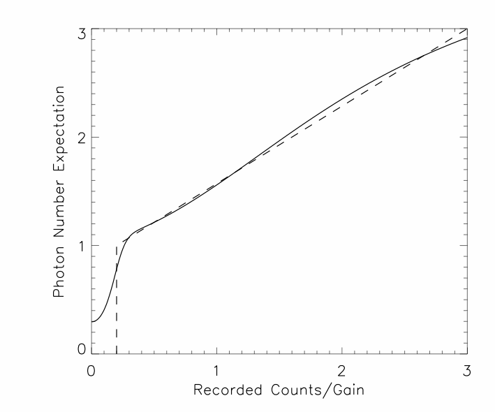
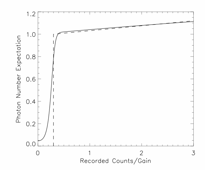
The noise factor for an EMCCD can be reduced by thresholding. In the simplest form, all pixel values less than some threshold at 2 to 3 times the readout noise are called 0, and all other pixel values are called 1. This simple thresholding only works well at photon rates less than about 0.25 photons per pixel per frame - the rate at which nonlinearity becomes significant at the 10% level (i.e. there are 0.1 times as many 2-photon events as 1-photon events). For slightly higher photon rates, there are lots of options to threshold but reduce nonlinearity, as shown in the following 2 examples.
Figure 1: Expected number of photons versus EMCCD output for an input where pixels have uniformly distributed photon arrival rates between 0 and 0.1 photons/pixel/frame, and a simple thresholding scheme (dashed line). The effective QE is 0.46 times ideal when using the raw EMCCD output, and 0.78 times idel when using the thresholding scheme.

Figure 2: Expected number of photons versus EMCCD output for an input where pixels have uniformly distributed photon arrival rates between 0 and 1 photons/pixel/frame, and a simple thresholding scheme (dashed line). The effective QE is 0.49 times ideal when using the raw EMCCD output, and 0.8 times ideal when using the thresholding scheme. Part of this gain is not real because of nonlinearities introduced in the thresholding. A full simulation is needed to really establish how effective this is….
Optimal Photon Rates
The above arguments mean that there are 2 obvious ways to run an EMCCD as an AO sensor:
- Simply use the raw output and accept the factor of 2 loss in effective QE.
- Run the sensor so that there are about ~0.5 photons/pix when locked with full AO at the magnitude limit
Option (1) involves sampling the PSF with approximately 2 pixels per FWHM (equal to lambda/subaperture_size). Option (2) is more complex. Reasonable AO performance in a classical AO system could be obtained with about 100 photons per subaperture at 250 Hz. These photons could be collected as 50 photons per frame at 500Hz or 25 photons per frame per subaperture at 1 kHz. The photon-rate is highest in the 500Hz case, so we shall use this as an example:
- 500Hz means up to 128×128 according to the Andor spec.
- 5 subapertures across the pupil means up to 25×25 pixels per subaperture.
- >10 pixels per 2 lambda/D is needed in this case to keep the photon rate low enough. For lambda=0.7 microns and D=0.2m, this gives 0.14“ per pixel, and a total field of view of 3.6” per subaperture.
The same numbers for the 1000Hz case means a slightly smaller field of view - maybe 3“ per subaperture.
Field-of-view Per Subaperture
When locked, the AO has to be spatially-filtered to maximize Strehl. This is a standard trick in extreme-AO in particular. If there are 6 actuators across a 1m aperture and you are correcting for H-band, then you can't correct spatial frequencies higher than 2.5 cycles per aperture. This means that the sensor field of view can only be +/- 0.8 arcsec. Any flux landing further from the fiducial point should be ignored and not used in the centroid calculation. Of course, this means that the minimum field of view is 1.6 arcsec, and anything larger just helps with acquisition and correcting large static errors. An open loop system is not so simple - in this case there is no tip/tilt on the wavefront sensor beams, and the field of view has to be at least about twice the FWHM of the seeing disk, or about 4 arcsec.
Table 1: Possible wavefront sensor configurations for a sub-aperture diameter of 0.2m. The pixel size is 16 microns, so a lenslet diameter of 250 microns corresponds to 78×78 pixels. A lenslet diameter of 0.4mm corresponds to approximately 128×128 pixels read out.
| Focal Length (mm) | Sampling at 700nm per l/D | Lenslet Diameter (mm) | Field of View (arcsec) |
| 18 | 3.15 | 0.250 | 3.6 |
| 18 | 2.63 | 0.300 | 5.1 |
| 13 | 2.28 | 0.250 | 4.9 |
| 36.5 | 4 | 0.400 | 4.5 |
For the system to work reliably in poor seeing, with a static wavefront error, the conservative approach is the row in bold (which is also the standard OKO C-mount lenslet array). Readout at about 1 kHz will work, but the canonical 0.5 photons/pix/sec to enable thresholding will only have about 10 photons/frame.


